Wiring Diagrams
Visual Wiring Diagram
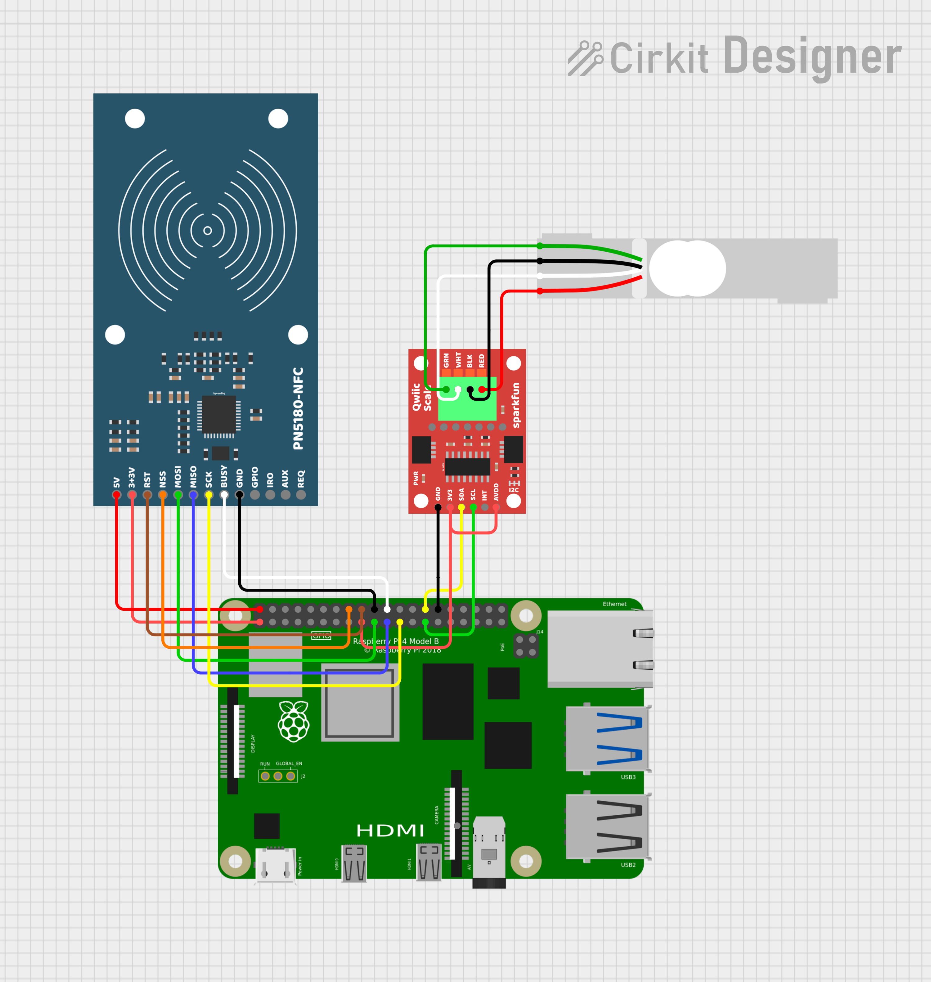
Below is the Fritzing-style wiring overview showing all SpoolBuddy components connected to a Raspberry Pi 4.
 by ouihq
 Diagram created with Cirkit Designer. Components: Raspberry Pi 4 Model B, PN5180-NFC reader (SPI), SparkFun Qwiic Scale NAU7802 (I2C), 5 kg single-point load cell.
Verify GPIO pins for your Pi model
All diagrams on this page are based on the Raspberry Pi 4 Model B. GPIO pin numbers and physical header positions are consistent across most Pi models, but always cross-reference against the pinout for your specific board at pinout.xyz before wiring. Some combinations (e.g. Pi 5, Pi Zero, CM4) may require adjustments.
PN5180 NFC Reader — Pi GPIO Wiring
The PN5180 communicates over SPI0 with a manual chip-select on GPIO23.
Dual voltage requirement
The PN5180 requires both 5 V and 3.3 V connections. Do not connect 5 V to the 3V3 pin — this will damage the module.
| PN5180 Pin | Direction | Pi GPIO | Pi Physical Pin | Wire Color | Notes |
|---|---|---|---|---|---|
| 5V | ← | — | Pin 2 | Red | 5 V power rail |
| 3V3 | ← | — | Pin 1 | Red | 3.3 V power rail |
| RST | ← | GPIO25 | Pin 22 | Orange | Hardware reset |
| NSS | ← | GPIO23 | Pin 16 | Yellow | Manual chip-select (dtoverlay=spi0-0cs) |
| MOSI | ← | GPIO10 | Pin 19 | Orange | SPI0 MOSI |
| MISO | → | GPIO9 | Pin 21 | Orange | SPI0 MISO |
| SCK | ← | GPIO11 | Pin 23 | Orange | SPI0 SCLK |
| BUSY | → | GPIO24 | Pin 18 | Blue | Busy/wait signal |
| GND | — | — | Pin 6 | Black | Ground |
| GPIO | — | — | — | — | Not connected |
| IRQ | → | GPIO17 | Pin 11 | Purple | Interrupt (optional) |
| AUX | — | — | — | — | Not connected |
| REQ | — | — | — | — | Not connected |
ASCII — PN5180 to Pi
  PN5180-NFC                              Raspberry Pi 4 GPIO Header
  ┌──────────┐                            ┌─────────────────────────┐
  │          │                            │  (active-low CS)        │
  │  5V    ──┼── Red ──────────────────── │── Pin  2  (5V)          │
  │  3V3  ──┼── Red ──────────────────── │── Pin  1  (3V3)         │
  │  RST   ──┼── Orange ──────────────── │── Pin 22  (GPIO25)      │
  │  NSS   ──┼── Yellow ──────────────── │── Pin 16  (GPIO23)      │
  │  MOSI  ──┼── Orange ──────────────── │── Pin 19  (GPIO10)      │
  │  MISO  ──┼── Orange ──────────────── │── Pin 21  (GPIO9)       │
  │  SCK   ──┼── Orange ──────────────── │── Pin 23  (GPIO11)      │
  │  BUSY  ──┼── Blue ────────────────── │── Pin 18  (GPIO24)      │
  │  GND   ──┼── Black ───────────────── │── Pin  6  (GND)         │
  │  GPIO  ──┼   (NC)                    │                         │
  │  IRQ   ──┼── Purple (optional) ──── │── Pin 11  (GPIO17)      │
  │  AUX   ──┼   (NC)                    │                         │
  │  REQ   ──┼   (NC)                    │                         │
  └──────────┘                            └─────────────────────────┘
Manual chip-select
SpoolBuddy uses dtoverlay=spi0-0cs in /boot/firmware/config.txt to disable the kernel's automatic CS so the daemon can manually toggle GPIO23 to meet PN5180 timing requirements.
NAU7802 Scale ADC — Pi I2C Wiring
The SparkFun Qwiic NAU7802 communicates over I2C bus 0 at address 0x2A.
I2C bus 0, not bus 1
SpoolBuddy uses /dev/i2c-0 (GPIO0/GPIO1), not the default /dev/i2c-1 (GPIO2/GPIO3). Make sure I2C-0 is enabled in your boot config.
| NAU7802 Pin | Direction | Pi GPIO | Pi Physical Pin | Wire Color | Notes |
|---|---|---|---|---|---|
| 3V3 | ← | — | Pin 17 | Red | 3.3 V power |
| GND | — | — | Pin 9 | Black | Ground |
| SDA | ↔ | GPIO0 | Pin 27 | White | I2C-0 data |
| SCL | ← | GPIO1 | Pin 28 | Yellow | I2C-0 clock |
| INT | → | — | — | — | Not connected |
| AVDD | ← | — | — | — | Bridge to 3V3 on board (see below) |
ASCII — NAU7802 to Pi
  SparkFun Qwiic NAU7802               Raspberry Pi 4 GPIO Header
  ┌───────────────────┐                 ┌─────────────────────────┐
  │                   │                 │                         │
  │  3V3  ────────── ─┼── Red ──────── │── Pin 17  (3V3)         │
  │  GND  ────────── ─┼── Black ────── │── Pin  9  (GND)         │
  │  SDA  ────────── ─┼── White ────── │── Pin 27  (GPIO0 / SDA0)│
  │  SCL  ────────── ─┼── Yellow ───── │── Pin 28  (GPIO1 / SCL0)│
  │  INT  ────────── ─┼   (NC)         │                         │
  │  AVDD ──┐         │                 │                         │
  │  3V3  ──┘ bridge  │                 │                         │
  └───────────────────┘                 └─────────────────────────┘
AVDD bridge (required)
On the SparkFun Qwiic NAU7802 board, you must solder a bridge between the 3V3 and AVDD pads. Without this bridge, the analog supply rail is unpowered and load cell readings will be unstable or zero.
Look for the two pads labeled 3V3 and AVDD on the back of the board — bridge them with a solder blob or short wire.
Load Cell — NAU7802 Wiring
A standard 4-wire load cell connects to the screw terminals on the SparkFun Qwiic NAU7802 board.
| Load Cell Wire | Color | NAU7802 Terminal | Function |
|---|---|---|---|
| E+ | Red | E+ | Excitation positive |
| E− | Black | E− | Excitation negative |
| A+ (S+) | Green | A+ | Signal positive |
| A− (S−) | White | A− | Signal negative |
ASCII — Load Cell to NAU7802
  Load Cell (5 kg)                     SparkFun Qwiic NAU7802
  ┌──────────────┐                     ┌───────────────────┐
  │              │                     │  Screw Terminals  │
  │  RED   (E+) ─┼── Red ──────────── │── E+              │
  │  BLACK (E−) ─┼── Black ────────── │── E−              │
  │  GREEN (A+) ─┼── Green ────────── │── A+              │
  │  WHITE (A−) ─┼── White ────────── │── A−              │
  │              │                     │                   │
  └──────────────┘                     └───────────────────┘
Wire color convention
Most single-point load cells follow the color convention above. If your load cell uses different colors, refer to its datasheet. The key is matching excitation (E+/E−) and signal (A+/A−) correctly.
Full System ASCII Wiring Diagram
                                    ┌──────────────────────────────────────┐
                                    │        Raspberry Pi 4 Model B        │
                                    │                                      │
                                    │  Pin 1  (3V3) ──────┬───────────┐   │
                                    │  Pin 2  (5V)  ──┐   │           │   │
                                    │  Pin 6  (GND) ──┼───┼─────┐     │   │
                                    │  Pin 9  (GND)  ─┼───┼─────┼──┐  │   │
                                    │  Pin 11 (GPIO17)┼───┼─────┼──┼──┼─ (IRQ, optional)
                                    │  Pin 16 (GPIO23)┼───┼─────┼──┼──┼─ NSS
                                    │  Pin 17 (3V3) ──┼───┼─────┼──┼──┼──┐
                                    │  Pin 18 (GPIO24)┼───┼─────┼──┼──┼──┼─ BUSY
                                    │  Pin 19 (GPIO10)┼───┼─────┼──┼──┼──┼─ MOSI
                                    │  Pin 21 (GPIO9) ┼───┼─────┼──┼──┼──┼─ MISO
                                    │  Pin 22 (GPIO25)┼───┼─────┼──┼──┼──┼─ RST
                                    │  Pin 23 (GPIO11)┼───┼─────┼──┼──┼──┼─ SCK
                                    │  Pin 27 (GPIO0) ┼───┼─────┼──┼──┼──┼─ SDA0
                                    │  Pin 28 (GPIO1) ┼───┼─────┼──┼──┼──┼─ SCL0
                                    │                 │   │     │  │  │  │
                                    └─────────────────┼───┼─────┼──┼──┼──┼─┘
                                                      │   │     │  │  │  │
     PN5180-NFC (SPI0)                                │   │     │  │  │  │
     ┌──────────────────┐                             │   │     │  │  │  │
     │  5V   ◄──────────┼─────────────────────────────┘   │     │  │  │  │
     │  3V3 ◄──────────┼─────────────────────────────────┘     │  │  │  │
     │  GND  ───────────┼───────────────────────────────────────┘  │  │  │
     │  RST  ◄── GPIO25 ┼─────────────────────────── Pin 22       │  │  │
     │  NSS  ◄── GPIO23 ┼─────────────────────────── Pin 16       │  │  │
     │  MOSI ◄── GPIO10 ┼─────────────────────────── Pin 19       │  │  │
     │  MISO ──► GPIO9  ┼─────────────────────────── Pin 21       │  │  │
     │  SCK  ◄── GPIO11 ┼─────────────────────────── Pin 23       │  │  │
     │  BUSY ──► GPIO24 ┼─────────────────────────── Pin 18       │  │  │
     │  IRQ  ──► GPIO17 ┼─────────────────────────── Pin 11 (opt) │  │  │
     └──────────────────┘                                         │  │  │
                                                                  │  │  │
     SparkFun Qwiic NAU7802 (I2C-0)                              │  │  │
     ┌──────────────────┐                                         │  │  │
     │  3V3  ◄──────────┼────────────────────────────── Pin 17 ───┘  │  │
     │  GND  ───────────┼──────────────────────────────── Pin 9 ─────┘  │
     │  SDA  ◄─► GPIO0  ┼────────────────────────────── Pin 27         │
     │  SCL  ◄── GPIO1  ┼────────────────────────────── Pin 28         │
     │  AVDD ◄── bridge ┼── (solder to 3V3 pad on board)               │
     │                  │                                               │
     │  E+  ◄───────────┼── RED wire ──── Load Cell                    │
     │  E−  ◄───────────┼── BLACK wire ── Load Cell                    │
     │  A+  ◄───────────┼── GREEN wire ── Load Cell                    │
     │  A−  ◄───────────┼── WHITE wire ── Load Cell                    │
     └──────────────────┘                                              │
                                                                       │
     Load Cell (5 kg single-point)                                     │
     ┌──────────────────┐                                              │
     │  RED   (E+)      │                                              │
     │  BLACK (E−)      │   (wired to NAU7802 screw terminals above)   │
     │  GREEN (A+)      │                                              │
     │  WHITE (A−)      │                                              │
     └──────────────────┘                                              │
                                                                       │
     3V3 rail shared ──────────────────────────────────────────────────┘
Required Boot Config
Add the following to /boot/firmware/config.txt (the SpoolBuddy installer does this automatically):
# Enable SPI with no automatic CS (manual GPIO23 chip-select)
dtparam=spi=on
dtoverlay=spi0-0cs

# Enable I2C bus 0 for NAU7802
dtparam=i2c_vc=on

# Enable I2C bus 1 (general purpose, usually already on)
dtparam=i2c_arm=on
After editing, reboot:
Post-Wiring Verification
After wiring all components, verify with these checks:
# Confirm SPI devices are present
ls /dev/spidev0.*
# Expected: /dev/spidev0.0

# Confirm I2C bus 0 is present
ls /dev/i2c-0
# Expected: /dev/i2c-0

# Scan I2C bus 0 for NAU7802 at address 0x2A
sudo i2cdetect -y 0
# Expected: "2a" appears in the grid
Then run the SpoolBuddy diagnostic scripts:
# PN5180 NFC diagnostics
sudo /opt/bambuddy/spoolbuddy/venv/bin/python \
  /opt/bambuddy/spoolbuddy/scripts/pn5180_diag.py

# Scale / NAU7802 diagnostics
sudo /opt/bambuddy/spoolbuddy/venv/bin/python \
  /opt/bambuddy/spoolbuddy/scripts/scale_diag.py
All green?
If both diagnostics pass, your wiring is correct. Proceed to Installation or Configuration.
Troubleshooting wiring issues
If diagnostics fail, double-check these common issues:
- PN5180 not detected: Verify 5 V and 3.3 V are both connected. Check MOSI/MISO aren't swapped. Confirm
dtoverlay=spi0-0csis in boot config. - NAU7802 not at 0x2A: Make sure you're on I2C bus 0 (GPIO0/GPIO1, pins 27/28), not bus 1. Check
dtparam=i2c_vc=on. - Scale reads zero: Solder the AVDD bridge on the SparkFun board. Without it, the analog rail has no power.
- Unstable NFC reads: Keep NFC wiring short. Long or loose jumper wires cause signal degradation.
Related Pages
- Hardware Requirements — Component overview and build notes
- Materials Required — Full bill of materials with shop links
- Installation — Software setup after wiring
- Configuration — Daemon and kiosk settings